
Whats new in 1.1 is that this revision replaces the ferrite transformer in the high voltage inverter, with a ferrite choke circuit, so the complicated part of building the custom transformer is gone. You can build this using shelf components, and the Gerbers files for making the PCBs are also included. Just send the gerbers to your favorite PCB manufacturer, get the BOM and start soldering. With just a couple of components, youll have an excellent dosimeter of wonderful performance.
Let me see if I can find an interested student.
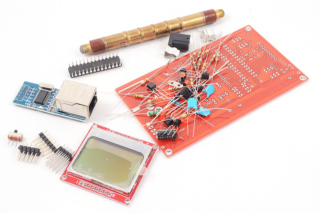
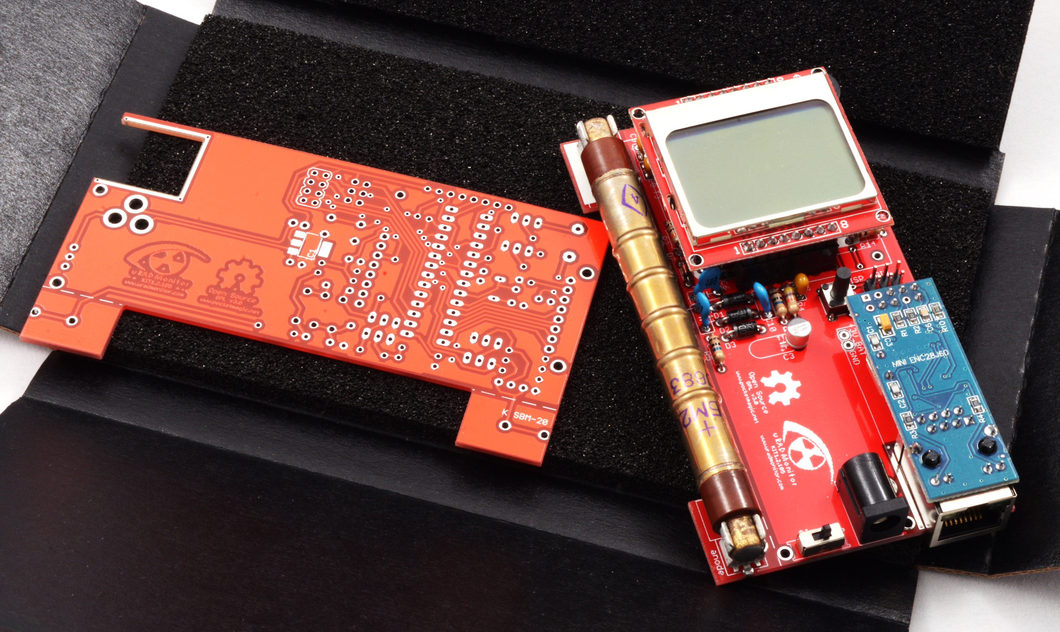
Finally an open source compact radiation dosimeter, that has an LCD and thus allows mobile use, but also comes with an Ethernet adapter so it can do radiation monitoring (uRADMonitorcompatible). This is a DIY Geiger Counter Kit, named the uRADMonitor KIT1, designed due to popular demand. Now, all those asking for a uRADMonitor Kit have a nice alternative in this device. This circuit uses a single layer PCB and only trough hole components, making the construction so much easier for all the DIY enthusiasts.
With the integrated Ethernet connectivity will send all measurements automatically via the Internet, to theuRADMonitor server, or to any backend you want. Add a battery and it can also be used as a portable dosimeter, showing all measurements on the LCD.
The software has been updated as well, having nice improvements in place like timeout for the LCD backlight or UI split into pages, to show all the relevant details and measurements grouped together. Just press the main button to navigate through them.
Last but not least, here comes the security. Initially, open source can be a source of vulnerabilities of the exposed system. We had to make sure the new open communication protocol is safe to use. Weve implemented API Authorisation…
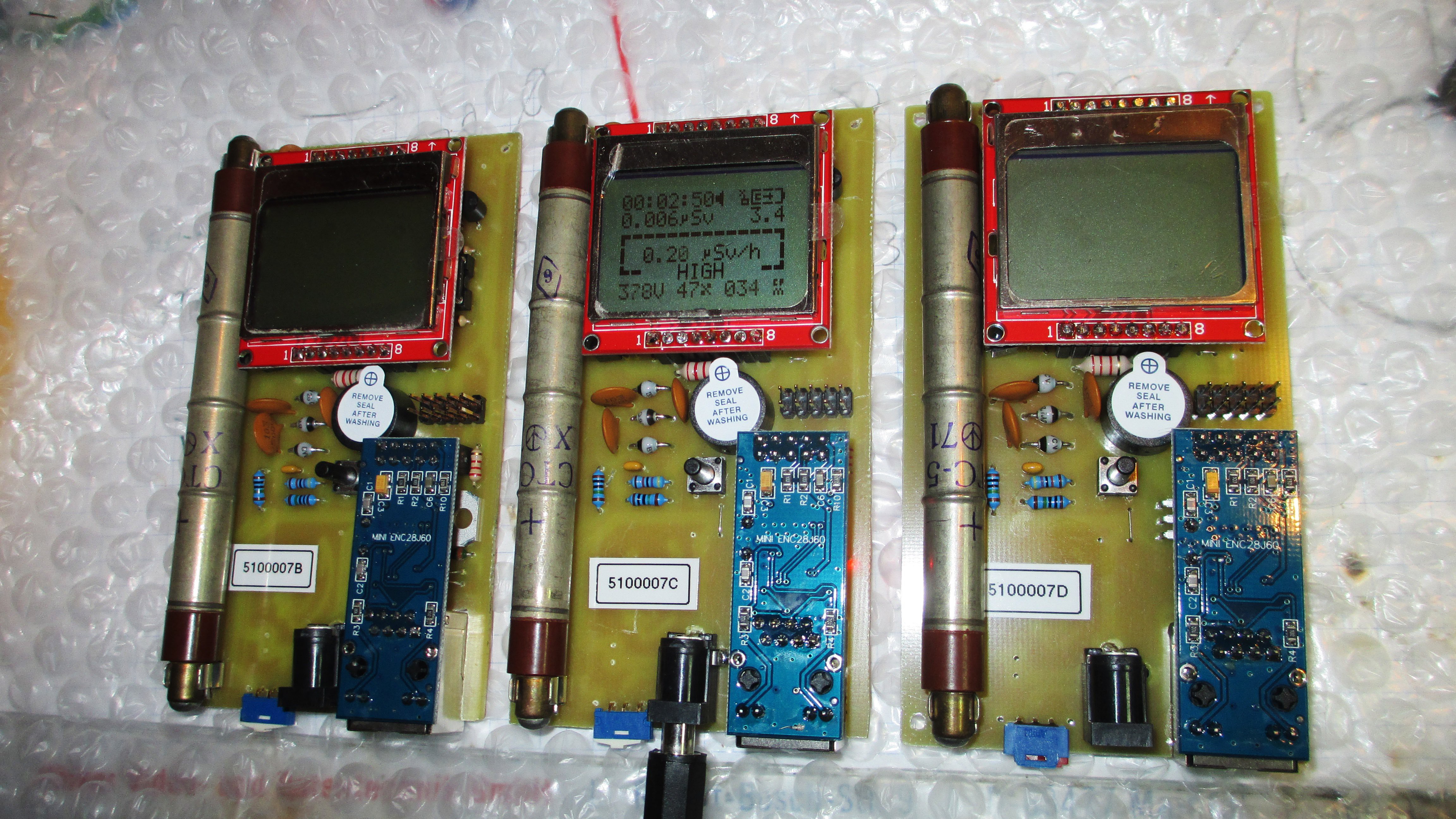
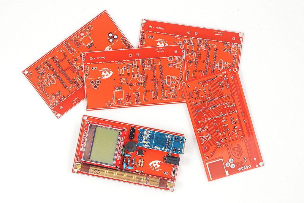
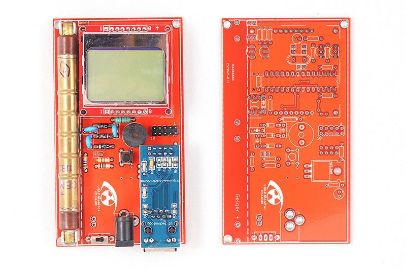
With so many changes on the server backend, we had to improve the KIT1 circuit and PCB. We tried to add many of the suggestionsreceived on the forum. From now on however, feel free to fork the original Github repository and do whatever you like with this open design. The new version is KIT1.2.105, and you can see the first design images below:
Adrian used the his KIT1 unit which came out nicely:
Hackaday.io projects you can buy in the Tindie maker marketplace
By default it comes with a SBM20 tube to measure Gamma radiation and has an extension slot (v1.2.105) to add additional sensors. The code on GITHUB offers support for the Bosch BME280 sensor by default.
It was time to add one missing thing to complete the work and that is certifications. First Iwanted was CE, offering extra trust to what this product is. So I started researching ways of accomplishing the CE tests with minimum costs. Iwas able to identify a company, discussions went well, Isend them the payment and the documentation and things started to move.
You are about to report the projectOpen Source IOT Platform, please tell us the reason.
Your application has been submitted.
So what happened with the github issues? WellWolferl1pointed out some issues with the values Ive been using. And indeed, he was right. Ichanged those right away, and this brought some immediate improvements, such as lower PWM duty cycle to the high voltage inverter, and lower power consumption:
The video shows the first prototype of version KIT1.0, built using the toner transfer method. As said, it was designed using through hole components, on a single layer PCB board.
Here are some pictures showing a few of them:
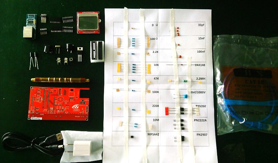
Check the BOM list and the schematics, and get all components. There are only a few, so this will be easy. Start soldering everything. This brings a lot of fun, as the entire design is done with through hole components, so easy to do with basic tools like just a soldering iron.
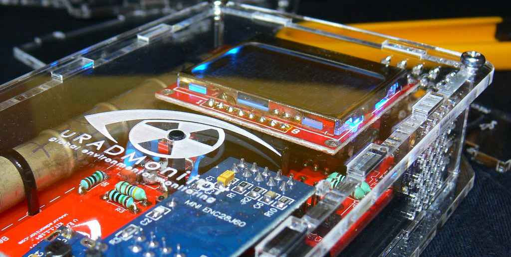
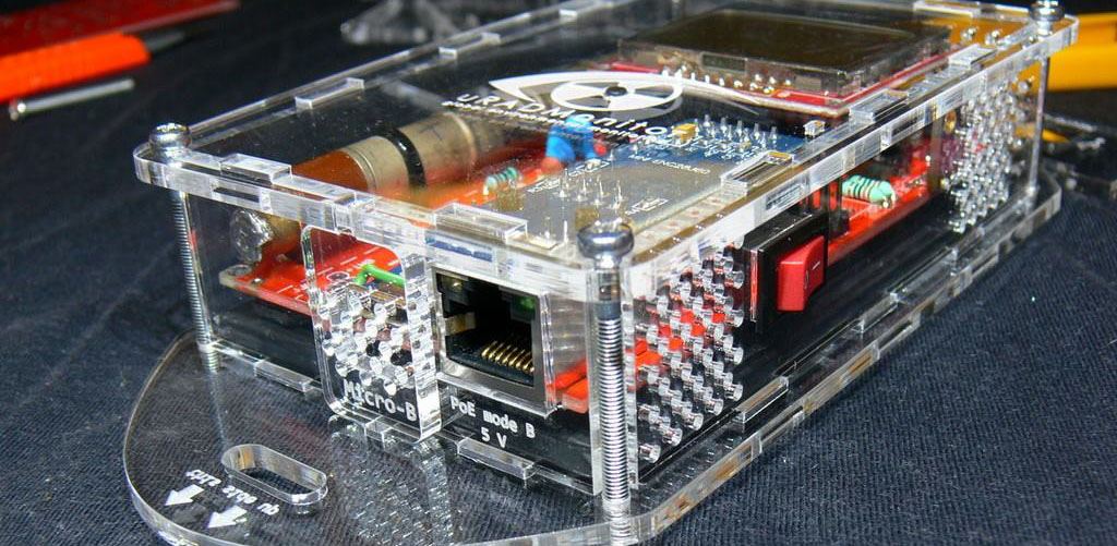
Transparent case made from plexiglass
Then theres the data accuracy which needs to be guaranteed to a reasonable degree by supervising and testing the hardware, something impossible with open, remote constructions. Making the server decide if the data is genuine or just some random useless bits was not an easy task.
What they did was a large number of tests to verify literally everything, from drop tests to EM interferences.
The GitHUB code comes with a dynamic ID allocation system, that means the units can join theuradmonitor networkautomatically.
But the lower duty cycle gives more margin to the inductor working interval, lowering the criticality of this component. His suggestions went further like using a 47M resistor in the high voltage divider circuit used for feedback, but Idecided to go with more common components.
Open the Source code repo and identify the latest PCB version. Take the Gerber files and send them to a PCB manufacturer or make them yourself: toner transfer works great and the boards were designed to be easy to make.
Any PCBs left? 🙂 If not, guess Ill have to find my ferric chloride 😀
Compile the code, and write the HEX to your board, using a 6 PIN ISP connector. For the fuse settings, if you followed the original design, youll need to set the external 8MHz crystal, and make sure the EESAVE fusebit is set.
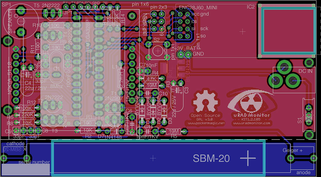
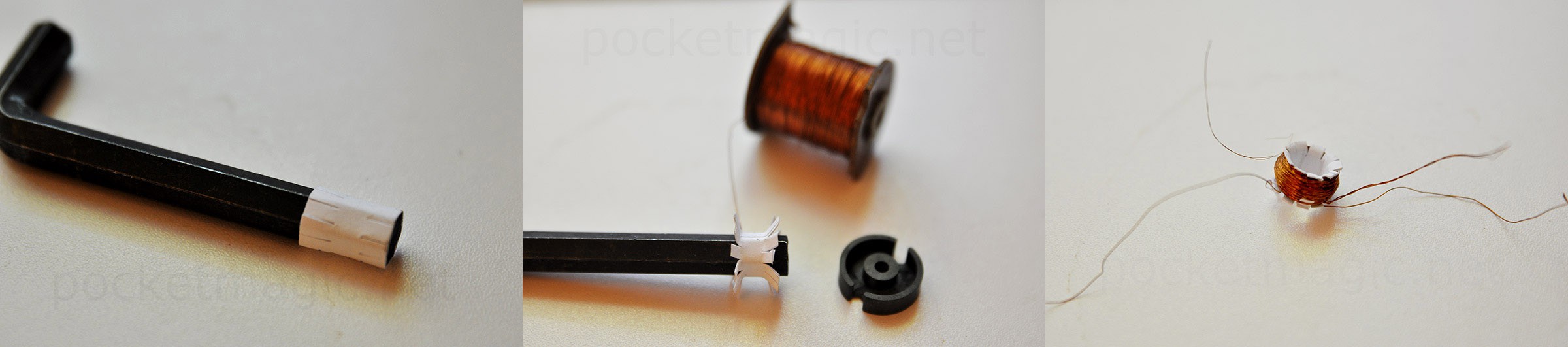
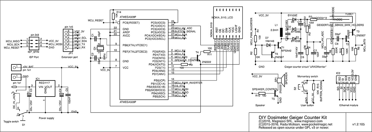
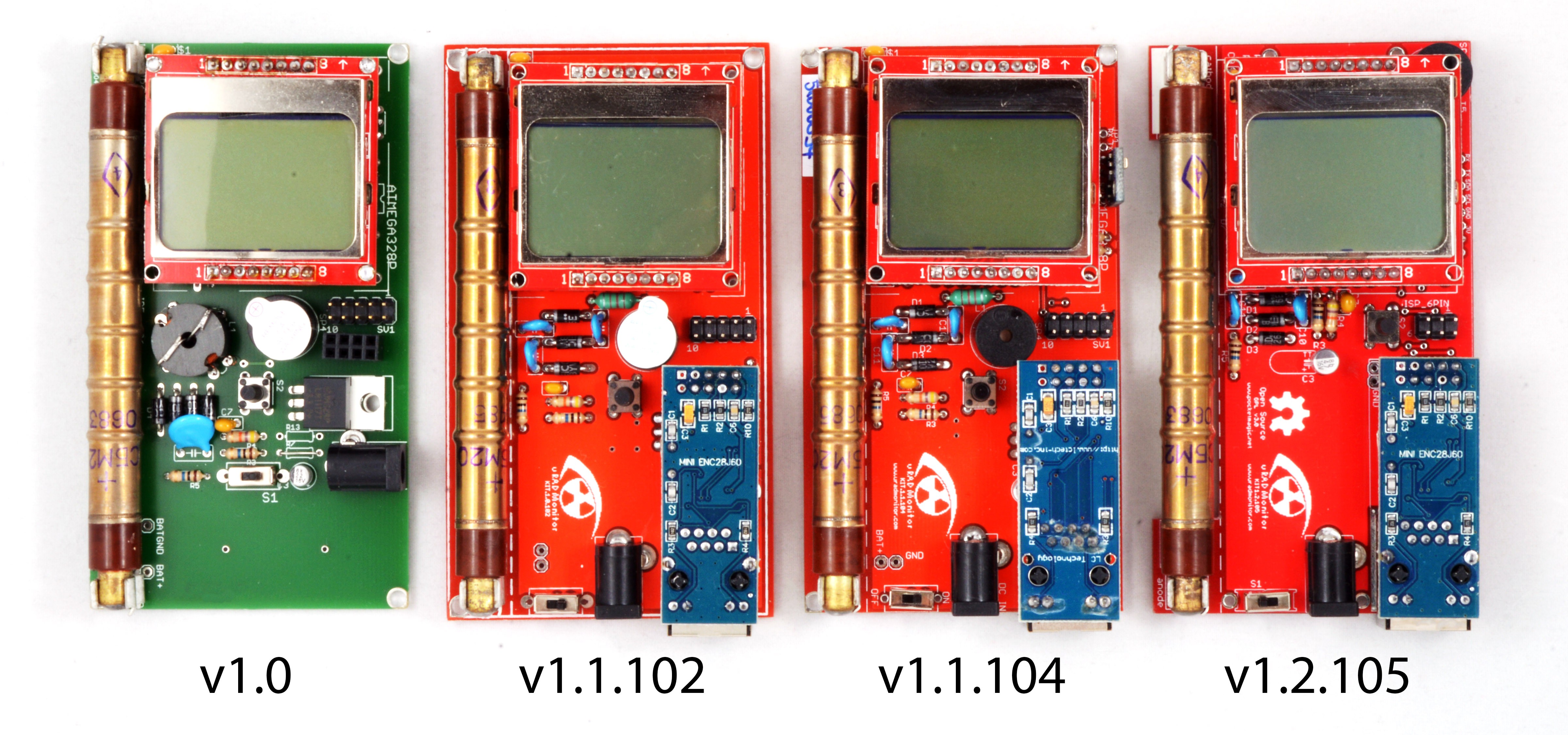
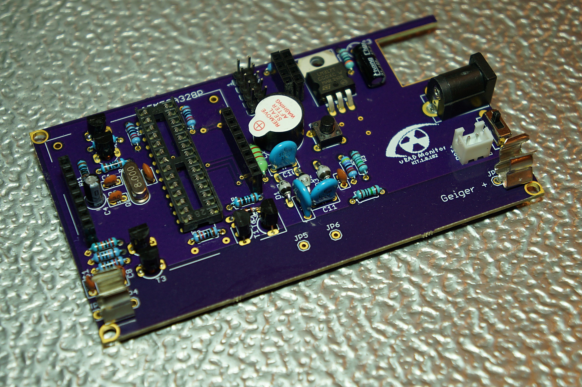
This was the most important change in the 1.1 versions, replacing the ferrite transformer with a simple inductor readily available in electronics shops. A voltage multiplier would compensate for the lower voltage of the new inverter, so we would still reach the 400V target needed by the Geiger tube. The switching transistor is blocked with a second PNP transistor to collapse the magnetic field on the coil faster, and generate higher voltage spikes. More on the development of a compact high voltage inverterhere. This approach was used in theuRADMonitor model Aas well, just with SMD components.
Discrete Semiconductors / Diodes and Rectifiers
As for the battery, probably everybody has access to some broken smartphones although the phone or display is broken, chances are good that the battery is still functional. You just have to hook up to the output of the charging module and the input of the voltage stabiliser and it is ready to use. Ive used one scavenged element from an old macbook battery. It contains 4 lithium cells, similar to the one onthis site. The cells are roughly the size of the kit1 pcb. This way, I saved all costs on charger + battery (0.3 euro).
Last week Ive assembled a KIT1 and posted some details about it to the forum. radhoo praised the article and asked me to share it on this blog, maybe will be helpful for the readers. So, here is an updated copy-paste from theoriginal post.
Power Management ICs / Linear Voltage Regulators and LDOs
In the end Igot the TEST PASS label, together with hundreds of pages of reports, documenting every technical aspect of the device and of the test, probably more then Iknew about the deviceI designed. The company Iused was BCTC in Shenzhen, and I am very happy with their professionalism and promptitude.
I also had to replace the originallm1117 voltage stabiliser, because it has a large dropout voltage, 1.1v. (this would be: 3.0 + 1.1 = 4.1v, maybe just 5% of the overall battery capacity. Not suited for my case ).
These 20 projects are the semifinalists of the Internet of Useful Things category of the 2017 Hackaday Prize.
Otakar built his from scratch, using version 1.1.103 design files:
The diy kit is based on the v1.1.104 pcb. It was made with minor modifications / improvements regarding the original model. First of all, Im a beginner in all this electronics and coding stuff, so if I wrote something stupid, please correct me. Im always open for constructive criticism. Second, sorry for my English, it is not my native language.
The max output current for the MCP1700 is 250mA, and the max input voltage is 6.0V. As the lithium battery never goes above 4.2v, its ok for me….
Real PoE connectivity, no additional cable / connector needed on the device side, just the rj45 connector
Hi Jacob,I gave away most of what I had! But Ill check that again
And the masterpiece created by Akos, that you saw in one of theprevious project logs:
With the device assembled, download the source code from Github.
Regarding the pcbs, after some emails, radhoo was so kind to send me 2 pieces, thank you again! And because i didnt want to destroy these beauties, all the modifications are made without hacking the pcb!
@Kumar, Abhishekthanks for the skull Kumar!Id be happy to send you a PCB if you want to build this. I still have a few extra.
Wow thanks- really interesting. So the higher voltage is developed by using the boost converter design and relies on self-inductance- the inductors resistance to change in current. Interesting to read about how two different transistors were needed, and then a voltage multiplier. Really cool to make so high a voltage using so small an inductor.
Theres a guy offering PCBs, ukewarrior, David Jones (Ohio, USA),
Tempted to build yours? I surely hope so! Thelatestdesign is available onGithub. It will only take you a few hours to do a toner transfer PCB and have some fun soldering this versatile IOT device:
To keep a safe distance between the aluminum foil of the battery and the bottom of the pcb (high voltage!), I used 4 self adhesive rubber shoes, like those intended for furniture.
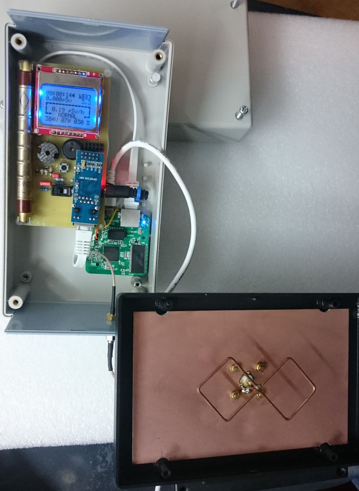
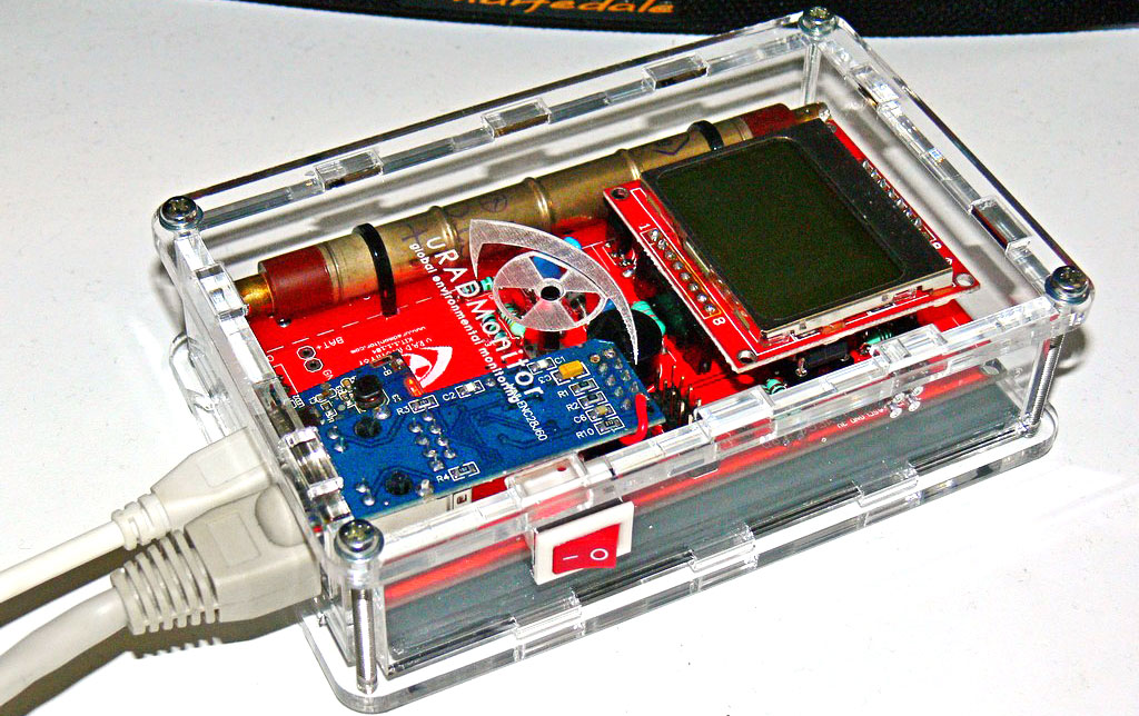
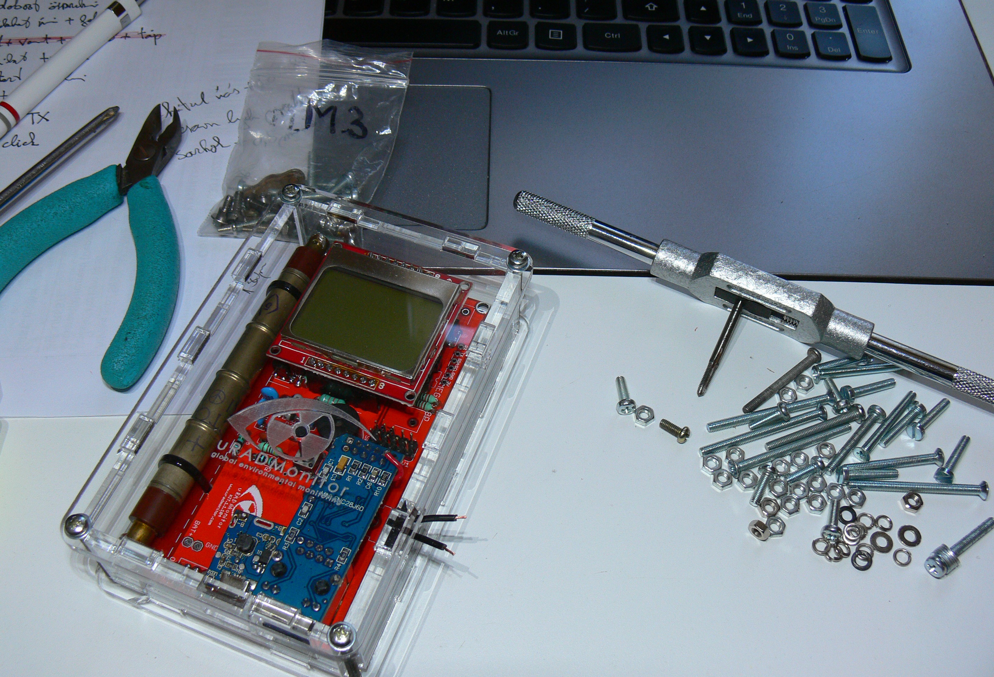
As the KIT1 is open source, talented community makers often brought upgrades to this versatile IOT platform. Here the work of Akos, that adapted the KIT for battery use and also built a plexiglass enclosure.
That would be great! Ill also check to see if I have any left.
With the extension port that exposes I2C, UART and power, you have the possibility to add a large number of additional sensors. Add the sensor driver code, and do the sensor reading in app/data.cpp and app/data.h initSensors() and readSensorsSlow(). To send the data online, see the code file misc/expProtocol.h for parameter IDs and how they are used in uRADMonitor.cpp line 350. More parameter IDs will be added based on demand.All previous KIT1 hardware versionsare compatible with the new firmware. For any questions and assistance, use theforum.
Hi just finished fixing a list of about 15 issues on github. This resulted in a new firmware version update and a new hardware iteration – minor with just a few values of some resistors changed.One of thesewas particularly interesting.
The community helped improving the design, with very many custom variants proving the utility of this IOT device, see the pictures inthis project log.
He used a lot of his personal timeto build and documentsomething better than the original. In the end he asked for nothing except to get access to the entire KIT1 source code so it can be improved further by the community of makers. We got the message and decided to act.
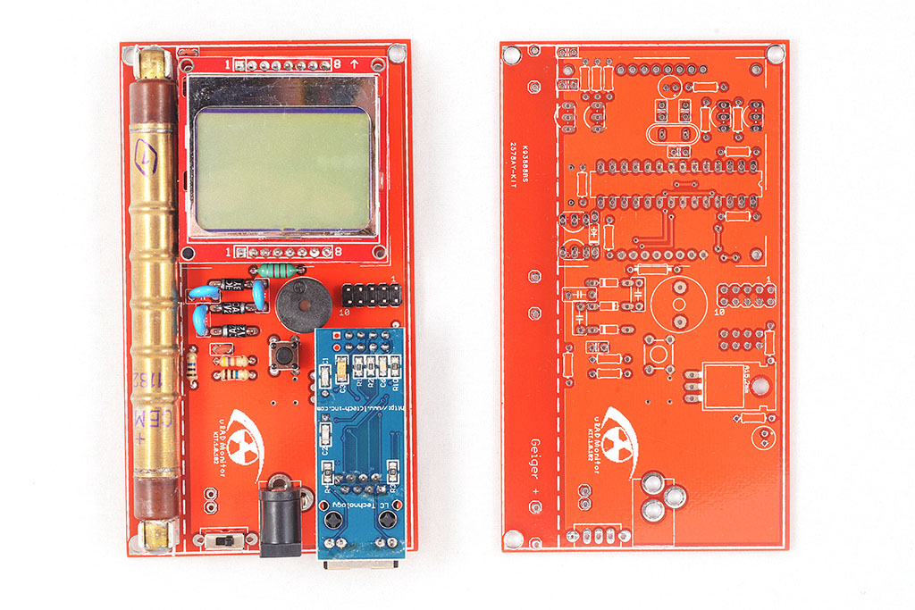
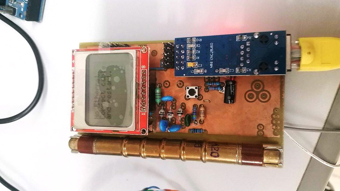
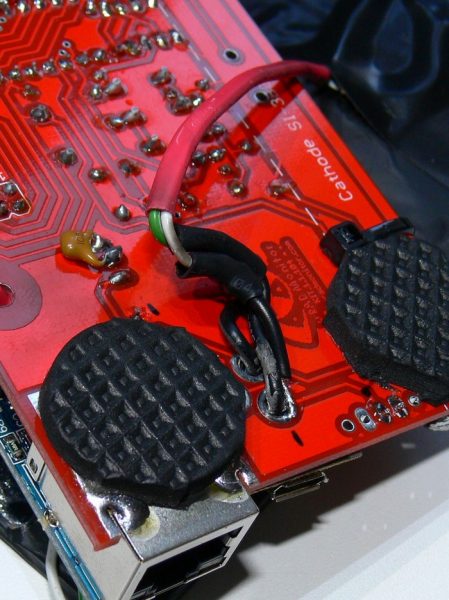
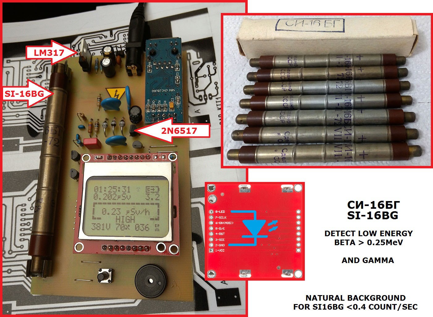
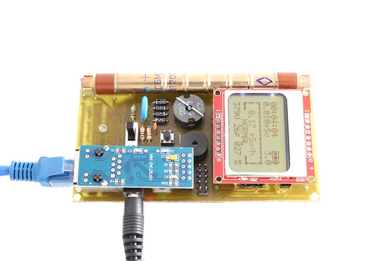
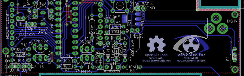
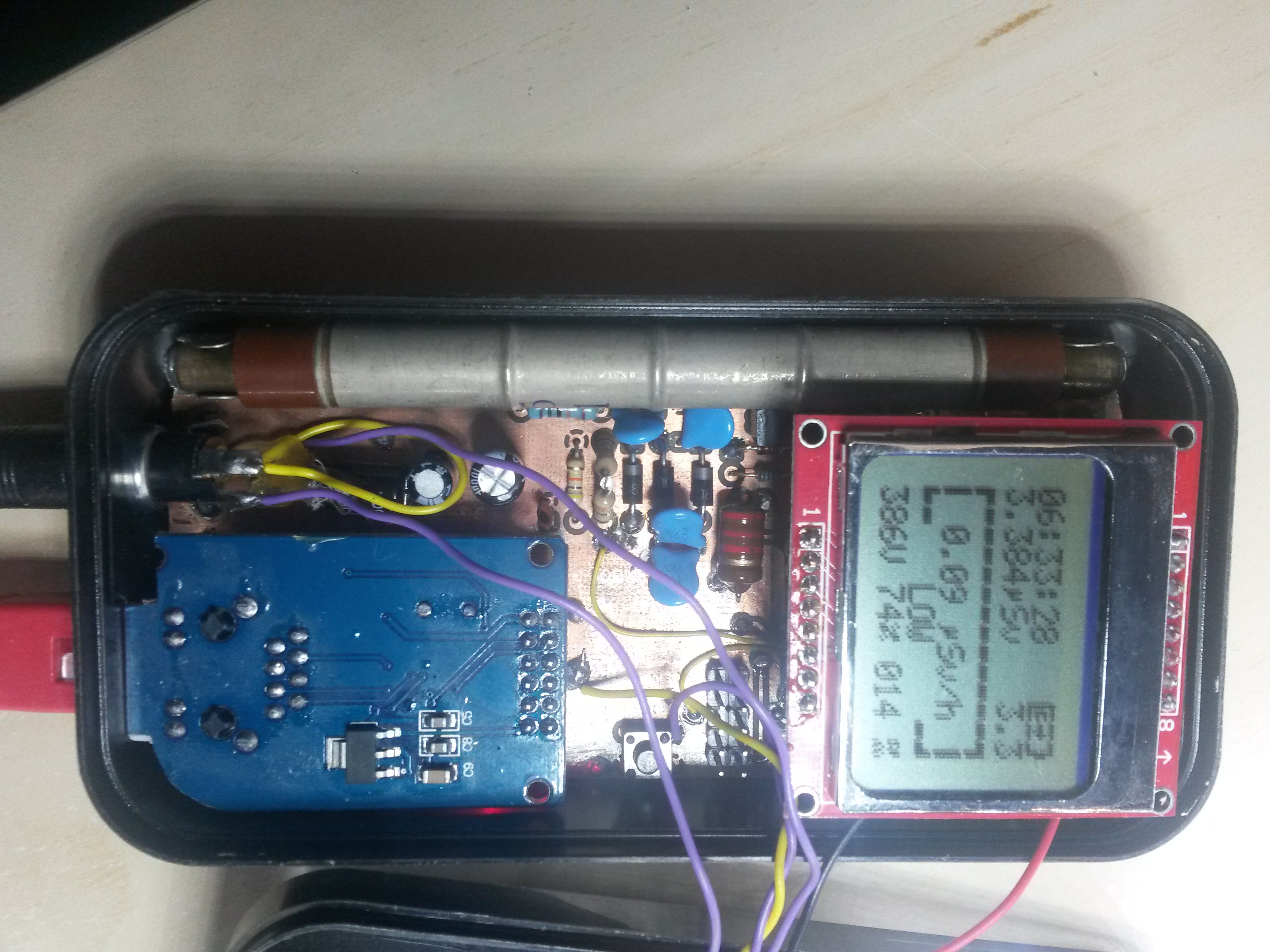
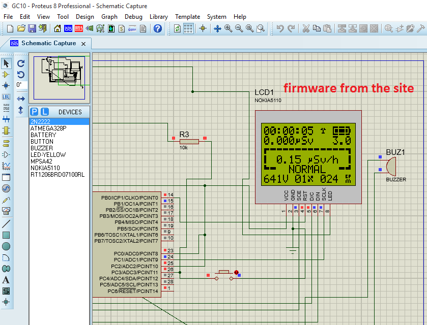
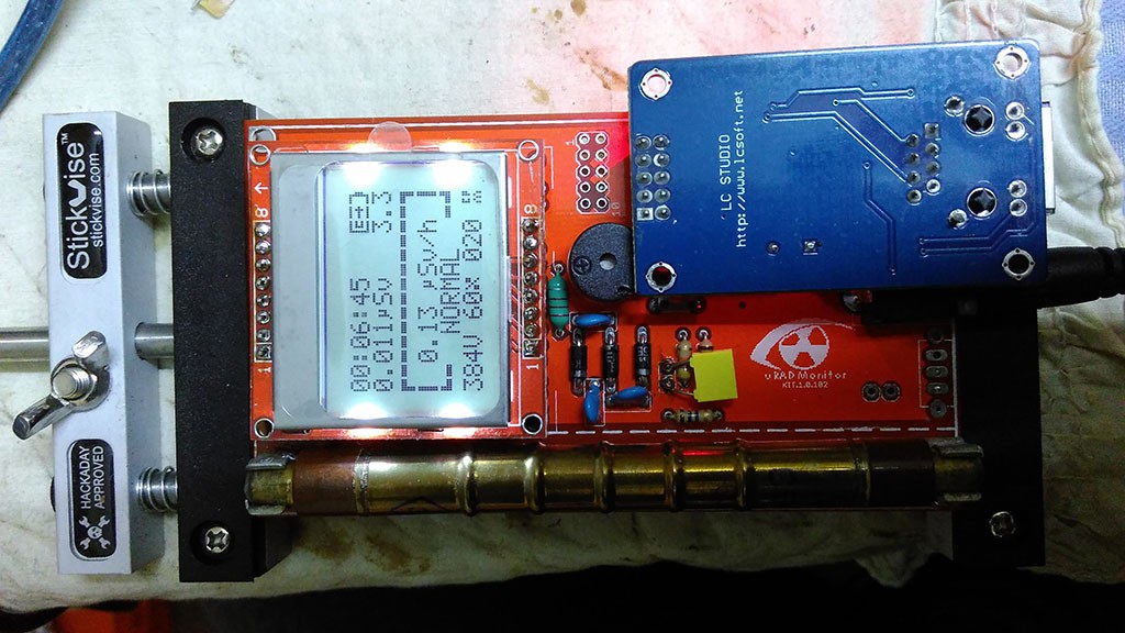
Theres a slot to mount aSBM-20 Geiger tube, a connector for the Ethernet module and one for theNokia 5110 LCDscreen. Both the LCD and the Ethernet adapter can be removed, allowing you to configure the final device: make that a portable dosimeter, a monitoring station or both. A speaker provides audible signals, including clicks and alarm, and a push button permits user interaction with the software. There are two pins at the bottom side that can be used to connect a 3V battery (two AA in series) or the unit can be powered using the DC connector, via a LM317 regulator and then it takes in any voltage in the 5-9V interval. The entire board runs on 3V, and the high voltage inverter boosts that up to 380V, configurable in software up to 600V if a different Geiger tube needs to be used.
Developing the KIT1 raised several problems in hardware and software, and those were solved with multiple PCB iterations.
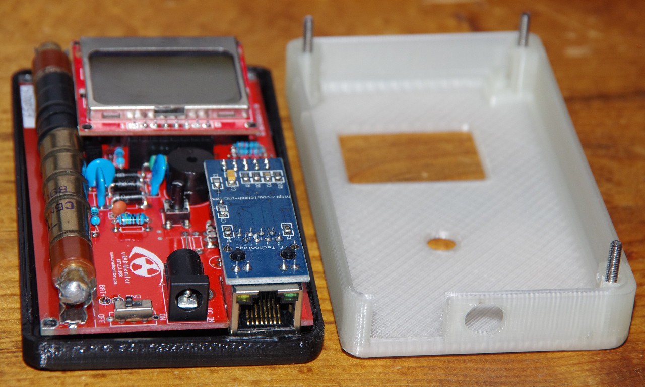
Chris and Frederik built a SMD variant, with a LIPO adapter to make the KIT1 fully portable. They also did a 3D printable enclosure:
reliable and high capacity rechargeable battery
These 20 projects are the semifinalists of the Best Product category of the 2017 Hackaday Prize.
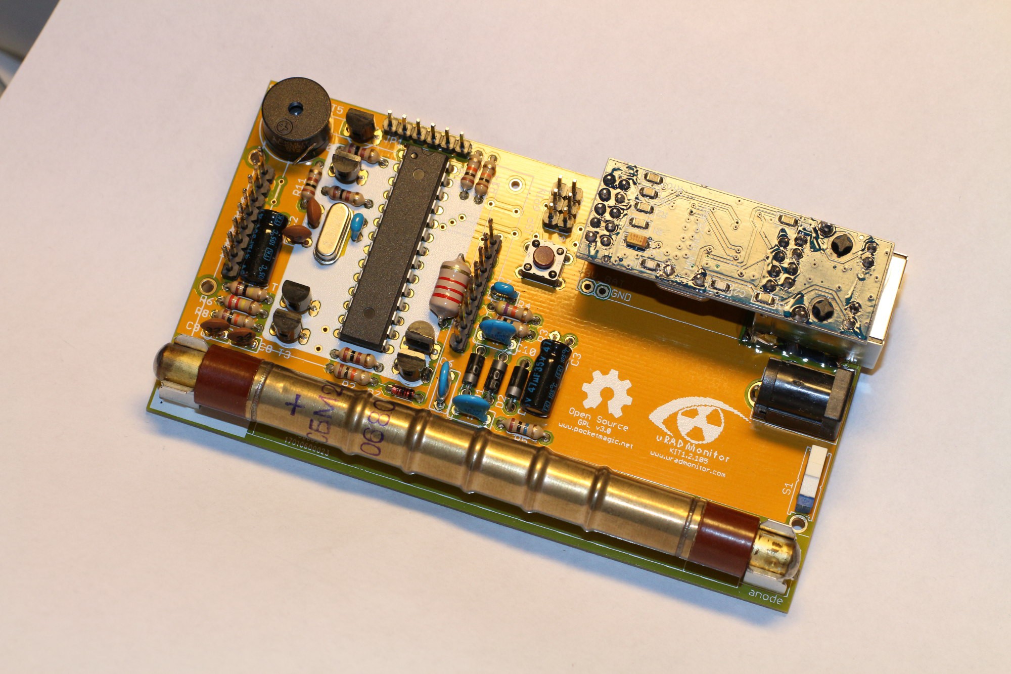
Malte built the new 1.2.105 on a beautiful orange PCB. Need to ask him where did he order it from. He also use a big fat inductor, that really cant go unnoticed:
See the above comment. Hope it helps.
Low dropout (0.17v) regulator
The extension port outputs voltage, I2C and UART connections to the microcontroller. You can use it for virtually any kind of sensor using these protocols, like PM2.5 sensors, UV sensors and so on.

Open-Source, easy to build IOT Dosimeter with sensors and Internet connectivity to centralise data.
Once your KIT1.2 circuit is complete, download the firmware code fromGithub. In config.h add your user-id and user-key from the dashboard.

Heres another one from Nicolas, including a custom enclosure:
Last but not least, here comes the security. Initially, open source can be a source of vulnerabilities of the exposed system. We had to make sure the new open communication protocol is safe to use. Weve implemented API Authorisation for all data uploads generated by the Open Source KIT1 units. Go to the dashboard, and create an account if you dont have one already. Youll need to use the user-id and the user-key listed there with your new uRADMonitor KIT1. If you go for the stock firmware, then you wont need them.
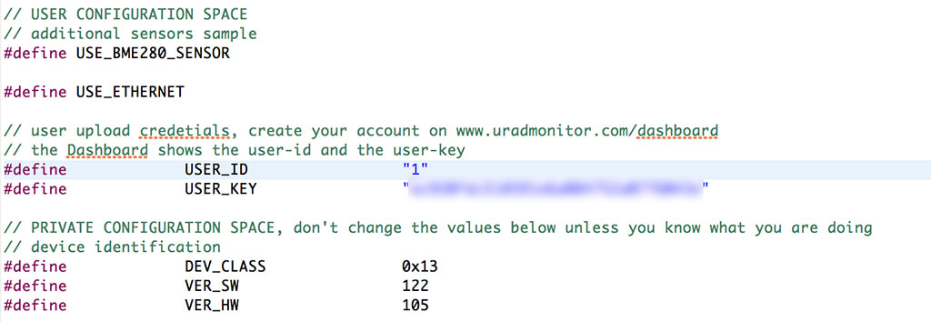
Your unit will receive a device ID allocated dynamically by the server. If you want to use a BME280 sensor, there is code already in place. Just make sure the USE_BME280_SENSOR is set in the config file.
Then theres the data accuracy which needs to be guaranteed to a reasonable degree by supervising and testing the hardware, something impossible with open, remote constructions. Making the server decide if the data is genuine or just some random useless bits was not an easy task.
@Bruce Landhi Bruce! Thanks for the skull. As I wrote to Kumar, I also want to offer you auRADMonitor KIT1PCB (free including shipping) , should you be interested in building one of these detectors. Using it you can join the global monitoring program on and keep track of Gamma levels at your location .
Hackaday Prize Entries using Microchip parts
This project addresses mostly DIY enthusiasts and IOT fans, however Ifelt it reached a point where it is mature. Thats because it got everything one HW product could possible want: multiple iterations, community support, community new features and new code and a high number of units distributed across the globe.
Intended as open source for those who want to build their own dosimeter with their own tools, this is an IOT device that can take several sensors and have the data centralised online. Thereadings are accessible via a RESTful API, or by connecting directly to the KIT1 unit, in the local LAN. This is useful when you want to monitor several locations, and plot charts or analyse the data.
Go to theuRADMonitor Dashboardand create a user account. Visit the API tab to retrieve the user ID and the user KEY that you need to add to the code.
Nowadays the standard power supply for handheld devices is the type b micro usb port. You can find them virtually anywhere. Also, it is fairly easy (and very cheap) to implement them into DIY stuff, using thesemodules. To add these without modifying the pcb, I simply glued them with 10 minutes epoxy. Not too smart, but will surely withstand the abuse of the backlash from the usb cable.
Most lithium batteries have anominal voltageof 3.6V (min 2.9V, max 4.2V). The recommended operating voltage for the KIT1 is min 3.0V, max 3.3V. To use the battery to the maximum, I opted for a 3.0V voltage regulator. It has to have ultra low dropout voltage, in order to maximize battery life.
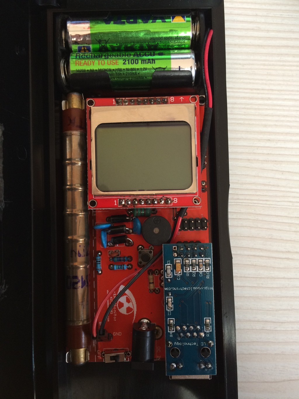
I built 2 kits: one for me and on for a friend. He asked to make it portable, because he will use it mainly on field, as a mobile unit, outdoors and on industrial working sites. This raised two challenges:
I already presented the advantages of the community support for this open source design in the previous logs. The KIT1 development took advantage of the creative effort of many makers out there.
Hackaday Prize Entries using Digi-Key parts
Version 1.1.103is not visible in the first picture, but you can see it below. 103 was supplied after thesuccessful indieGogo campaignin 2016, both as a solderable KITs and a readily assembled units.
Youll find the complete code there as well, or you can use thisdirect link. More information is available on…
As discussed ingtonvia the comments the other day, the high voltage inverter in these units jumps from 3.3V input to a configurable output voltage that is now set to 380V to fit the SBM-20 Geiger tube. To achieve this long jump, some components are critical to the design, such as the MPSA42 transistor and the 2.2mH inductor. For the latter, some of those building this circuit were having some issues, not being able to obtain the target voltage, or in some cases needing to change (lower) the inductor frequency to get the last push to the target. Idid my best to indicate the right sources for the inductors, but in some cases this was not enough.
a robust but not too bulky case
Compile the code, and use an usbAsp programmer (or any other that works) and burn the fuses and the software into the microcontroller.
I wanna see how measurements levels here in Goiania city where I live….There were a radioactive incident in 1987. Is there any pcb left?
Tino, did an amazing job building 3 units from scratch:
Yet, another example of team work, making this product better. Open source rules!
Sulleys unit running on 2 AA batteries (like originally planned):
Really interesting project! How do you step up the 3.3v to 370v?It looks like there are only a view diodes – is it multiple voltage doubling circuits?
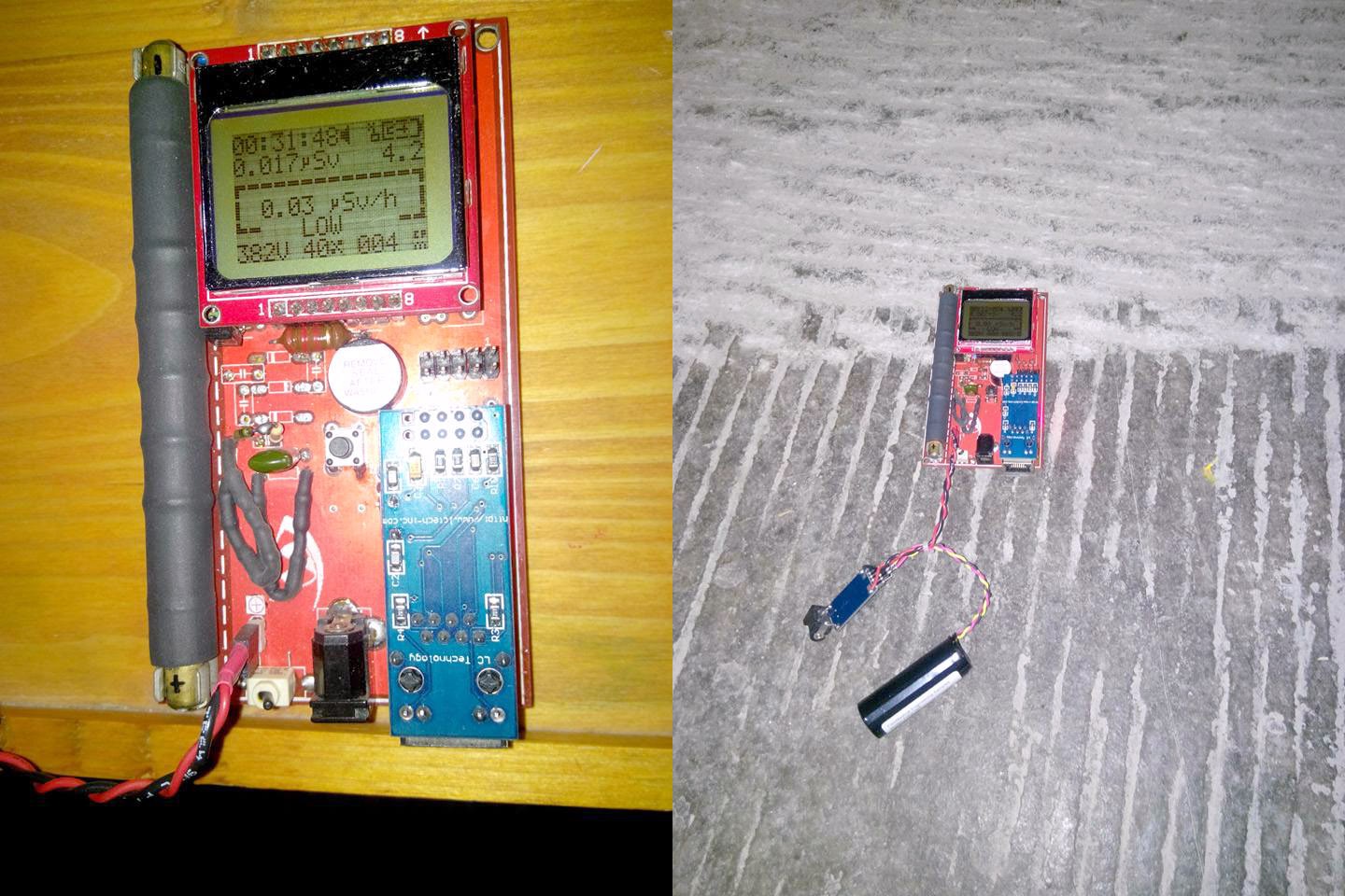
And who said the KIT1 cant talk wireless? The design is made for the ENC28J60, but this clever maker found a solution to connect to its wireless router via the waves:
Iuse the AVR to generate a PWM signal with frequency and duty controlled by code. The frequency is set (fixed) to match the ferrite core of the inductor while the duty cycle is adjusted automatically during runtime so the output voltage is set at the desired value (380V). The output voltage is measured constantly via a resistive voltage divider and an ADC port on the AVR. The switching transistor is turned off by a coupled NPN to collapse the magnetic field on the coil faster, and so achieving higher voltage amplitudes. Then the few HV diodes and caps form a voltage multiplier to reach 380V. From code the voltage can be set to any desired voltage, max on this circuit is about 500V with 3V in, and more with 5V in. More on how Ideveloped this on my blog:
uRADMonitoris Big Data. Hundreds of detectors worldwide are collecting measurements every minute, and the server deals with millions of entries in its database every day. The database holdingKIT1data was designed for efficiency: only the minimum data goes in. One reason for open sourcing was to allow customising the KIT1 units with additional sensors. We had to adapt the server backend in this regards, and now theres an expandable list of parameters that can be uploaded.
This project was created on 10/04/2015 and last updated 6 months ago.
In order to follow projects & hackers or give likes
These are just of the few that were built. Initially,v1.0used a ferrite transformer for the High Voltage inverter needed to boost the 3V Vcc up to 400V required by the Geiger tube. Making such a transformer was a difficult task, that would limit the production capabilities. The secondary needed about 400 turns of very thin wire:
Microprocessors, Microcontrollers, DSPs / ARM, RISC-Based Microcontrollers
Open Source means collaborative work, joined effort leading to extraordinary things. Recently we saw how a talented maker fromOradea, Romaniapushed his KIT1 uradmonitor unit to the limit!
Heres an interesting, highly customised KIT1 version:
Some simulations of the circuit and firmware some other guys were doing:
The best thing about this update is the high voltage inverter update, that now uses a choke instead of the custom ferrite core transformer. So all this can be built in just a couple of minutes with readily available components, for a low cost.
Become a memberto follow this project and never miss any updates
The new design is more compact, so if you want to add a battery youll have more space. The arrangement of some components has been optimised and the regulator becomes the single SMD component on this otherwise exclusively through hole components PCB. As soon as we get the first of the new PCBs, well add more pictures with them.

Incorporated lithium battery
After a lot of research, I bought theMCP1700-3002E/TO regulator. It has a very low dropout, only 0.17V! We get: 3.0 + 0.17 = 3.17v, so I can use around 95% battery capacity. So far, so good.
uRADMonitor is Big Data. Hundreds of detectors worldwide are collecting measurements every minute, and the server deals with millions of entries in its database every day. The database holdingKIT1data was designed for efficiency: only the minimum data goes in. One reason for open sourcing was to allow customising the KIT1 units with additional sensors. We had to adapt the server backend in this regards, and now theres an expandable list of parameters that can be uploaded.
Hi, this looks cool ! Im living in north west Japan and sometimes pop into Fukashima ( not near the disaster area but still.. I should order one of these boards and build !!! 🙂
Heres another KIT1 built from scratch, most likely using toner transfer:
Are you sure you want to remove yourself as a member for this project?
This is probably the easiest way one can take to have a good digital radiation dosimeters. It was built for the SBM20 Geiger tube, widely available at reasonable prices. Alternatively, other tubes can be used and the PCB has been designed to fit various tubes. The high voltage inverter can also go as high as 600V, to accommodate any custom tubes. The version currently posted on HaD is the latest, the KIT 1.1 and brings several improvements as presented in the project description.
One beautiful 3D Printable enclosure, available onThingiverse:
1.1.104brings an extension port, used to connect additional sensors. TheRepository on GITHUBoffers default code with a driver for the Bosch BME280 sensor included by default.
UpdatedBOM, with the components I used (if something is missing, please let me know).
This is probably the easiest and most convenient way for any DIYenthusiast to build a radiation dosimeter for personal purposes or for joining the uRADMonitor network of detectors.
Project owner will be notified upon removal.
Note: I bought the components for these kits from local stores, the best available quality. Hence, the visual aspect of these components may differ from the originals shipped with the KIT1. I measured / tested all of them before soldering, to make sure everything is up to the specs.
This is the KIT1, an Open Source IOT Dosimeter, that can be used both as a portable detector, but also as a monitoring station to upload readings over the internet. By default it uses a Geiger tube to detect radiation. When used as a portable detector, readings are displayed on the LCD. There is also a speaker that beeps on radiation events or is used to sound an alarm for higher readings. When used as a monitoring station, it functions as an automated detector, that doesnt need a separate computer to send the readings. Designed for makers, this circuit will provide excellent performance comparable to commercial detectors or better. The extension slot allows adding more sensors.
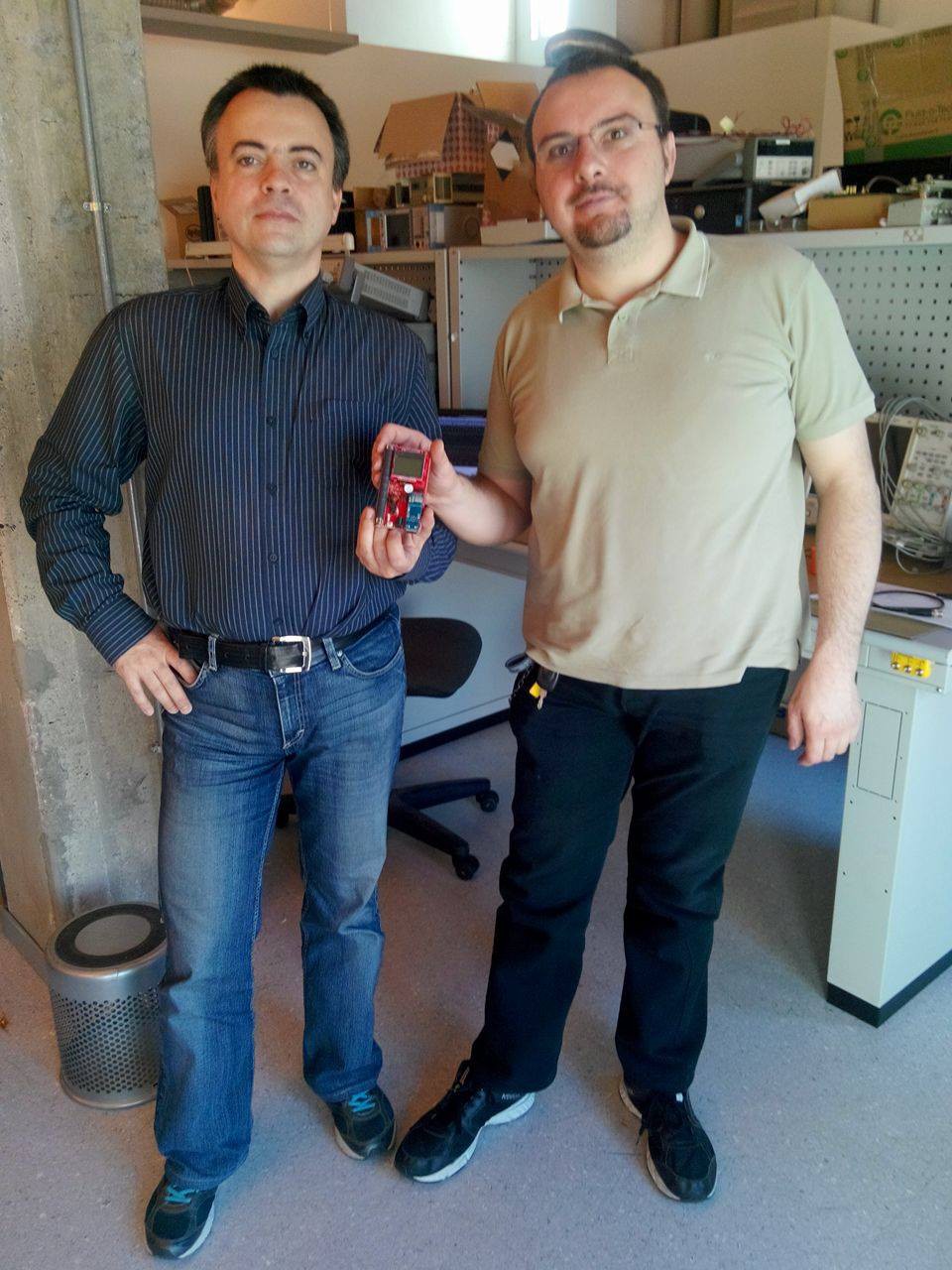
Heres Horia and Fabio, good friends from forum, with their fresh new KIT1, ready to take some of Fabios X-RAY experiments:
Yes, but look at the Global radiation monitoring networkor thePortable environmental monitorto see work of art using SMD components. The former doesnt even use a multiplier.
Builtin battery charger module + micro usb port
To compile the code, please useEclipseand theAVR Crosspack pluginas well as theAVRDudesoftware. For uploading the HEX code, you can use the versatileusbAsp programmerconfigured for 3.3V!
1.2.105is a new kind of beast. The board has been reworked, the speaker and central button were moved, the PCB under the tube has a milling layer to avoid any interferences on the radiation detection capabilities, and the ISP connector went from the redundant 10pin variant to the 6pin standard.